
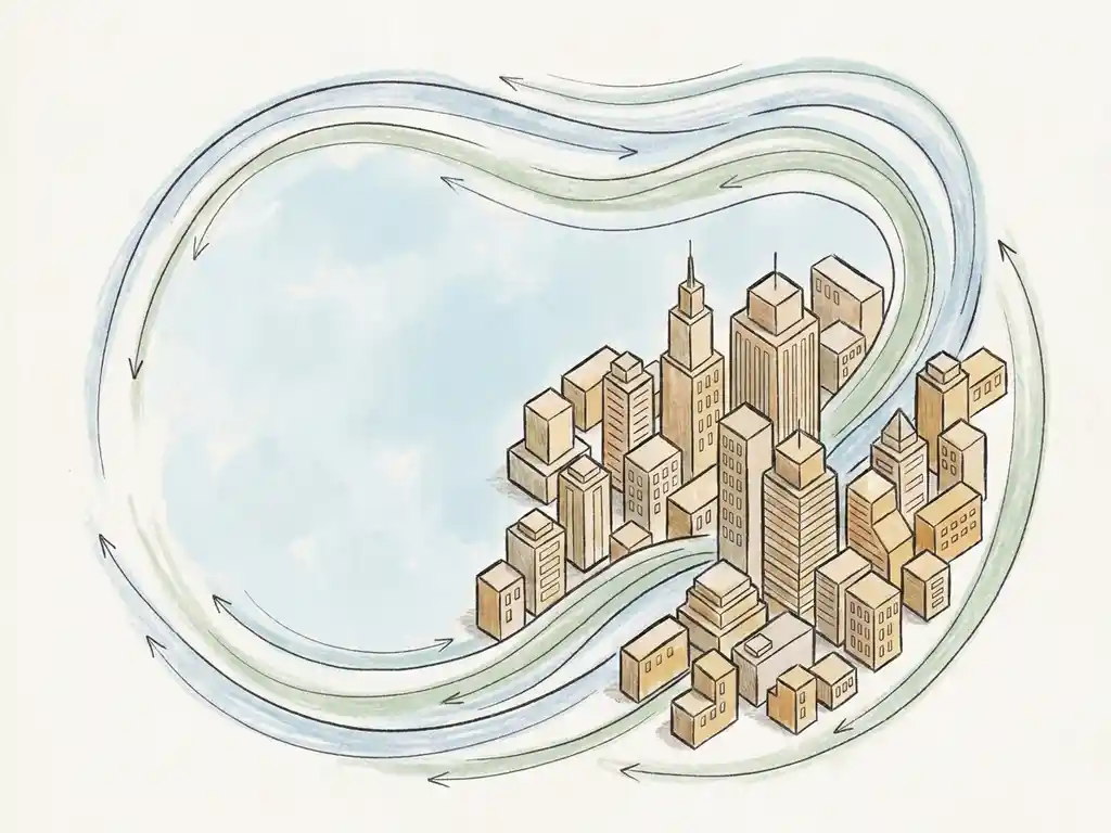
Engineers apply wind engineering in complex urban sites by combining CFD (Computational Fluid Dynamics) simulations with detailed 3D models of the surrounding built environment to predict how wind behaves at pedestrian level. Urban sites are more demanding than open-terrain assessments because buildings, streets, and public spaces interact with airflow in ways that are difficult to predict without simulation. The sections below cover the main challenges, methods, criteria, and design responses that engineers work through on a typical urban wind project.
What makes urban sites more challenging for wind engineering?
Urban sites are more challenging for wind engineering because the built environment creates unpredictable airflow patterns that do not exist in open terrain. Buildings accelerate, redirect, and channel wind in ways that vary significantly depending on building height, spacing, street orientation, and the presence of open plazas or gaps in the urban fabric.
A few specific effects make urban wind assessment particularly complex:
- Downdraught from tall buildings: A building that is more than twice the height of its immediate surroundings pushes high-level wind down to street level, creating strong gusts at the base of the facade.
- Corner acceleration: Wind wraps around building corners and accelerates, often producing the highest pedestrian-level wind speeds in an area.
- Street canyon effects: Narrow streets with tall buildings on both sides can channel wind like a pipe, especially when streets run parallel to the prevailing wind direction.
- Plaza exposure: Open squares with more than 25% of their windward perimeter unobstructed are significantly more prone to wind nuisance.
- Height differences between adjacent buildings: A height difference of more than 30% between neighbouring towers tends to generate turbulence and downwash at the transition zone.
These effects interact with each other, which is why assessing one building in isolation rarely gives a complete picture. The wind conditions at street level are always a product of the entire surrounding context.
What methods do engineers use to assess wind in urban environments?
Engineers use two main methods to assess wind in urban environments: wind tunnel testing and CFD simulation. Wind tunnel testing uses a physical scale model placed in a controlled airflow environment and works well for individual buildings and smaller masterplans. CFD simulation runs entirely on a computer and is the standard approach for large-scale urban areas where a physical model is not practical.
For city-wide or area-wide studies, CFD is the preferred method. It allows engineers to model an entire urban district, run simulations for multiple wind directions, and produce detailed maps of wind conditions across every street, square, and public space in the study area. Our wind engineering services cover both approaches, depending on the scale and regulatory requirements of the project.
The choice between methods is not always either/or. Some projects combine both: CFD for the area-wide picture and wind tunnel testing for specific facade pressure measurements or structural load calculations required by Eurocode EN1991-1-4.
How does CFD simulation work for a complex urban wind study?
A CFD simulation for an urban wind study works by building a detailed 3D model of the area, dividing the surrounding air volume into millions of small cells, and solving the equations of airflow across all of those cells for each wind direction. The result is a complete picture of how wind behaves at every point in the model domain.
The process runs in three main steps:
- 3D model construction: The model is built from geodata sources such as building footprint databases and height models. Existing and permitted buildings are included; details smaller than one metre are typically omitted because they have negligible influence on pedestrian-level results. A simplified outer ring of 250 metres surrounds the core study area to ensure wind enters the model correctly.
- Mesh generation: The air volume above and between buildings is divided into cells. For large urban studies, this mesh can contain hundreds of millions of cells, with the finest resolution (around 0.25 m) near building surfaces and coarser cells (up to 64 m) at the domain boundary. Five prismatic layers are extruded from wall surfaces to capture the velocity gradient near the ground accurately.
- Simulation and post-processing: Simulations run for each wind direction using meteorological data from sources such as KNMI. The raw results are processed into colour-coded maps showing wind speed, wind comfort class, and, where relevant, pollutant dispersion or ventilation potential. These maps are directly presentable to clients, planners, and permit authorities without further translation.
For a city-scale study, the computational demands are substantial. The Rotterdam urban wind study we carried out with the Municipality of Rotterdam involved a mesh of over 583 million cells and required more than 21 hours of mesh generation on over 1,000 CPU cores. That kind of scale is only feasible with dedicated high-performance computing infrastructure and a high degree of process automation.
Which wind comfort criteria apply to urban pedestrian areas?
The two main wind comfort criteria used in urban pedestrian assessments are NEN 8100 (used in the Netherlands) and the Lawson criteria (used internationally, including in the UK and for projects assessed under City of London or Leeds planning policy). Both systems classify wind conditions at pedestrian level based on how frequently wind speeds exceed defined thresholds.
Under NEN 8100, the key metric is the probability that wind speed at eye height (1.75 m) exceeds 5 m/s. This produces five classes:
- Class A: Exceedance less than 2.5% of the time. Suitable for all activities including sitting.
- Class B: Exceedance 2.5 to 5%. Suitable for sitting and strolling; moderate for walking through.
- Class C: Exceedance 5 to 10%. Suitable for sitting; moderate for strolling; poor for walking through.
- Class D: Exceedance 10 to 20%. Moderate for sitting; poor for most activities.
- Class E: Exceedance above 20%. Poor for all activities.
Wind danger is assessed separately using the 15 m/s threshold. Locations where this speed is exceeded too frequently are classified as hazardous regardless of their comfort class. The Erasmus Bridge and sections of the Willemsbrug in Rotterdam are well-known examples of locations that reach this threshold.
For projects outside the Netherlands, the Lawson criteria apply a similar logic but use different threshold speeds and activity categories. Knowing which norm applies to your project depends on where it is located and which planning authority is involved. Our fluid dynamics consultancy has over 21 years of experience advising on exactly this question across the Netherlands, Belgium, the UK, and beyond.
What happens when wind assessment results reveal a hazard?
When wind assessment results reveal a hazard, engineers work through a hierarchy of design measures, starting with the most effective interventions at the urban planning level and moving down to localised fixes if larger changes are not possible. Solving a wind problem at building level is significantly harder when the urban layout has already been fixed.
The mitigation hierarchy typically runs as follows:
- Urban layout (most effective): Clustering towers so they shield each other, keeping height differences between adjacent buildings below 30%, and orienting streets diagonally or perpendicular to the prevailing wind to avoid channelling effects.
- Building volume and orientation: Aligning the narrowest facade perpendicular to the prevailing wind, avoiding building openings or passages that face the dominant wind direction, and using setbacks. A setback needs to be at least 5 metres deep for a 100-metre building to be effective; the setback roof level itself is not suitable for occupancy because it sits directly in the downwash zone.
- Aerodynamic design: Rounded or tapered facades allow wind to flow around the building rather than pushing it downward. Covered walkways and galleries protect pedestrians directly, but the area immediately adjacent to the gallery remains exposed.
- Local interventions: Screens redirect wind locally but accelerate it at their edges. Planting (trees, hedges) improves comfort but is not a primary safety measure and loses its effectiveness in winter when deciduous trees shed their leaves, precisely when wind speeds are highest.
- Function relocation: Sometimes the simplest fix is moving an entrance, terrace, or playground a short distance away from the most exposed location.
The important principle here is that wind problems discovered late in the design process are always more expensive and more constrained to fix. A small adjustment to building orientation or massing at concept stage can eliminate a hazard that would otherwise require significant facade engineering or expensive public realm interventions later.
When should wind engineering be integrated into the design process?
Wind engineering should be integrated into the design process as early as possible, ideally at the concept or schematic design stage before building volumes and orientations are fixed. The earlier wind is considered, the more design options are available and the lower the cost of any adjustments.
In practice, many projects commission a wind study only when a permit application requires one. This is understandable, but it means wind issues are sometimes discovered when changing the design is already expensive. A quick scan at the early design stage, using simplified geometry, can flag potential problems and inform layout decisions before they become locked in.
For projects in the Netherlands, NEN 8100 defines when a formal wind comfort study is required as part of a permit application. For projects in the UK, Lawson-based assessments are typically required by planning authorities for tall buildings or large area developments. Either way, starting the conversation with a wind engineer at the point when massing options are still open gives you the most flexibility to respond to findings without disrupting the programme.
How Actiflow helps with wind engineering in complex urban sites
We specialise in exactly this type of project: urban sites where the interaction between buildings, streets, and public space makes wind behaviour difficult to predict without proper simulation. Here is what we bring to it:
- Full-scale CFD capability: From a single high-rise to a city-wide masterplan, we run advanced virtual wind tunnel simulations and produce colour-coded maps that are ready to submit to municipalities or share directly with clients and planners.
- Regulatory expertise: We know NEN 8100 for Dutch projects and the Lawson criteria for international work, including the UK, Gibraltar, the Middle East, and Southern Europe. We advise you on which norm applies and what the permit authority will expect.
- Early-stage involvement: We can start with a quick scan at concept stage to inform design decisions, and scale up to a full assessment when the project reaches permit stage.
- Speed and flexibility: For regular clients, we set everything aside to start the next day if the project timeline demands it. Internal automation means we can deliver results faster without compromising quality.
- Large-scale urban experience: We carried out the comprehensive wind study for the city of Rotterdam, one of the most detailed urban wind assessments completed in the Netherlands, covering pedestrian comfort, urban ventilation, heat stress, and air quality in a single integrated study.
Curious how we can help with wind engineering on your project? Contact us and we will be happy to discuss your project and help you find the right approach. You can also find out more about our team and background on our about us page.
