
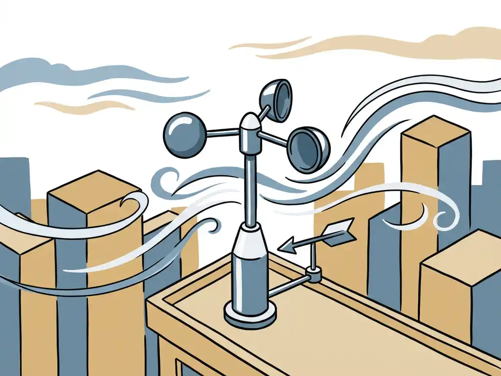
The most reliable methods for measuring urban wind speed are CFD (Computational Fluid Dynamics) simulations, physical wind tunnel testing, and on-site field measurements — each suited to different project scales and purposes. For large urban areas, CFD is the method of choice because it can model an entire city district in detail without requiring a physical model. Smaller, single-building studies often combine wind tunnel tests with CFD to validate results. The sections below break down how each method works, where it falls short, and how to choose the right approach for your project.
Which measurement methods give the most accurate urban wind data?
The most accurate urban wind data comes from combining CFD simulations with on-site measurements and, where scale allows, physical wind tunnel tests. No single method is perfect on its own. CFD gives you full spatial coverage and flexibility, wind tunnel tests provide physical validation, and field measurements capture real-world conditions that models sometimes miss. The best results come from using these methods in combination, with the choice depending on project scale, budget, and the level of regulatory scrutiny involved.
For wind engineering projects at neighbourhood or city scale, CFD has become the standard because it can process enormous areas with high spatial resolution. A single CFD study of a 5-kilometre urban district can produce wind speed data at pedestrian height across thousands of locations simultaneously — something a wind tunnel simply cannot replicate at that scale. Field measurements then serve as a reality check, confirming that the model behaves the way the real city does.
How does CFD simulation compare to physical wind tunnel testing?
CFD simulation and wind tunnel testing are both reliable methods, but they serve different purposes. Wind tunnel testing uses a physical scale model placed in a controlled airflow, making it well-suited to individual buildings or smaller masterplans where detailed physical accuracy matters. CFD runs entirely on computer hardware, making it the practical choice for large urban areas where building a physical model is not feasible.
The table below summarises the key differences:
| Method | Best suited for | Key advantage | Main limitation |
|---|---|---|---|
| Wind tunnel test | Individual buildings, smaller masterplans | Physical, tactile validation | Scale constraints, costly physical model |
| CFD simulation | Large urban areas, city-wide studies | Full spatial coverage, flexible scenarios | Requires careful setup and validation |
| Field measurement | Validation, existing buildings | Real-world data | Limited spatial coverage, weather-dependent |
CFD also offers a practical advantage when design changes are needed mid-project. Adjusting a digital model takes hours; rebuilding a physical wind tunnel model takes weeks. For projects under time pressure, that flexibility matters. Software such as OpenFOAM, using a steady-state solver and an SST k-omega turbulence model, produces results that align closely with wind tunnel benchmarks when the model is set up correctly.
What are the limitations of on-site wind measurements in cities?
On-site wind measurements in cities are limited by spatial coverage, weather dependency, and the complexity of urban airflow. A measurement mast or anemometer captures wind speed at one fixed point — it tells you nothing about what is happening 20 metres away around the corner of a building. Urban wind patterns are highly localised, which means a handful of sensors rarely gives you a complete picture of pedestrian-level conditions across a development site.
There are also practical constraints. Measurements take time to accumulate statistically meaningful data, and the results reflect the specific weather conditions during the measurement period — not necessarily the full range of wind directions and speeds that a site experiences over a year. This is why field measurements are most useful as a validation tool rather than a primary data source. You use them to confirm that a CFD model is performing correctly, then rely on the simulation for the broader spatial analysis.
When should a wind assessment use multiple measurement methods?
A wind assessment should use multiple measurement methods when the project is large, regulatory stakes are high, or the results will directly influence major design decisions. Combining CFD with field measurements or wind tunnel data gives you both the spatial coverage you need and the physical confidence that your model is accurate.
In practice, multi-method assessments are most useful in these situations:
- Large area developments where CFD covers the full site and field measurements validate the model at key locations
- High-rise buildings in complex urban settings where local acceleration effects need physical confirmation
- Permit applications under NEN 8100 or Lawson criteria where the methodology needs to withstand regulatory scrutiny
- Existing buildings with complaints where field data documents the problem before modelling solutions
- Projects where wind tunnel testing was done earlier and CFD is used to extend the analysis to a wider area
The general principle is straightforward: the higher the consequence of getting it wrong, the more value there is in cross-checking methods. For a standard single-building comfort assessment, well-validated CFD is usually sufficient. For a city-wide study or a high-profile development in a sensitive location, combining methods gives you a more defensible result.
What inputs are needed to run a reliable urban wind simulation?
A reliable urban wind simulation needs accurate 3D geometry, validated meteorological data, and a correctly configured computational mesh. Missing or approximate inputs in any of these areas will reduce the accuracy of the results — sometimes significantly.
Here is what goes into a well-set-up urban CFD model:
- 3D building geometry: Built from geodata sources such as 3DBAG, BRT TOP10NL, and AHN for Dutch projects. Existing and permitted buildings are included; details smaller than one metre are typically omitted because they have negligible effect on pedestrian-level results.
- Surrounding context: An outer ring of approximately 250 metres around the study area, modelled as simplified extrusion volumes, ensures that wind enters the model correctly rather than being distorted at the boundary.
- Meteorological input: For Dutch projects, the NPR 6097 dataset (1963–2002) is legally required for NEN 8100 permit procedures. The DOWA dataset (2008–2017) is more recent and can be broken down by season, which is useful for comfort studies focused on public space quality.
- Computational mesh: Cell sizes in the pedestrian zone typically range from 0.25 m to 4 m, with prismatic layers extruded from wall surfaces to capture the velocity gradient in the atmospheric boundary layer accurately.
- Turbulence model and solver settings: A steady-state incompressible solver with an SST k-omega turbulence model is the standard for urban wind studies. Reference wind speed and height must match the meteorological data used.
Getting the geometry right is often where studies run into trouble. Outdated building data or missing permits can lead to a model that does not reflect the real or planned urban environment. Checking the 3D model against current planning documents before running simulations saves time and avoids having to rerun expensive calculations. You can find an overview of what a full wind study process looks like on the Actiflow website.
How do wind measurement results affect building design decisions?
Wind measurement results directly shape decisions about building height, orientation, facade treatment, and public space layout. When a wind assessment identifies problem areas — high pedestrian wind speeds, dangerous acceleration zones, or poor ventilation — designers have a clear hierarchy of interventions to work through, starting at the urban planning level and working down to the building and its immediate surroundings.
At the urban planning level, results influence street orientation, building clustering, and height transitions between adjacent buildings. A useful rule of thumb: if a building is more than twice the height of its surroundings, it is more likely to cause wind problems at street level. Keeping height differences between neighbouring buildings below 30% reduces the risk of the so-called Manhattan effect, where wind is channelled and accelerated between towers.
At the building level, results guide decisions such as:
- Facade orientation: Avoiding the widest facade perpendicular to the prevailing wind direction
- Setbacks: Effective when at least 5 metres deep for a building of approximately 100 metres in height
- Passages and openings: Minimising openings aligned with the dominant wind direction to avoid pressure shortcuts that accelerate airflow
- Canopies and covered walkways: Useful for protecting pedestrians directly, though they shift the downwash to the canopy edge rather than eliminating it
- Planting: Effective for improving comfort, but not a substitute for structural measures and less effective in winter when deciduous trees lose their leaves
The timing of a wind assessment matters enormously here. Wind problems identified at the concept design stage can be resolved with relatively minor adjustments to massing or orientation. The same problems discovered after detailed design is complete often require costly rework. Integrating wind analysis early — ideally before building volumes are fixed — gives design teams the most flexibility to act on the results.
How we help you measure and manage urban wind speed
We bring together all three measurement methods — CFD simulation, wind tunnel testing, and field measurement — depending on what your project actually needs. Our team has over 21 years of experience in wind engineering across the Netherlands, Belgium, the UK, and beyond, and we know which method, which norm, and which level of detail is appropriate for each situation.
Here is what working with us looks like in practice:
- We advise you on the right assessment method from the start — whether that is a NEN 8100 comfort study, a Lawson-based assessment for international projects, or a large-scale area study
- We build accurate 3D models from current geodata and planning documents, so simulations reflect the real or planned environment
- We produce colour-coded maps and clear visual output that you can share directly with clients, planners, or permit authorities without translation
- We flag wind issues early in the design process and give you concrete mitigation options — not just a list of problems
- We work at any scale, from a single high-rise to a city-wide masterplan, and we are known for fast turnaround without cutting corners on quality
Curious how we can help with measuring urban wind speed? Contact us — we would be happy to discuss your project and help you find the right approach. You can also find out more about us and how we work.
